BL47XU Experimental hutch 2 (EH2)
問い合わせ番号
INS-0000001378
There are two experimental tables. The schematic diagram of the arrangement of two tables is shown in Fig. 1. On the upstream table, there are two X-Y-Z stages. On the downstream table, there are four X-Y-Z stages. These stages are driven by each pulse motor. For example, the resolution of the X-Y-Z stages is 2 µm and 0.08 µm/pulse in the Y-Z direction and X direction respectively at full step mode. For general purpose, we have 4-jaw slit, solid-state detector, scintillation counter, ion chamber, He-Ne laser, X-ray cameras (middle resolution: pixel size 6 µm and high resolution; pixel size 0.5 µm), and data acquisition system. A pinhole chamber (pinholes and slits are switchable in vacuum at a distance of 40 m from light source) has been installed in the optical hutch.
- Microtomography (micro-CT) experimental setup
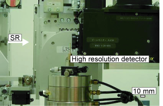
Upstream table is normally used for the X-ray microtomography system consists of sample stage and image detector stage. Air-bearing type sample rotation stage is used. The wobbling accuracy of the sample rotation stage is less than 0.2 µm. A visible-light converted type image detector (called as Beam Monitor) is used as data acquisition. The spatial resolution is about 1 µm. The maximum field of view is about 1 mm × 1 mm. It takes about 2-3 hours for one CT scan.
- Microbeam (Scanning microscopy)
Downstream table is normally used for the microbeam experiment. A Fresnel zone plate is used as the focusing device. Prove size is 0.5 µm (vertical) × 0.3 µm (horizontal), and the focal depth is about 1 mm. Useful energy range is 7~15 keV. X-ray flux of the prove is about 109 photons/s in maximum. Ionization chambers and silicon drift detector (SDD) are prepared as the detector.
 Fig. 2. X-ray microtomography setup
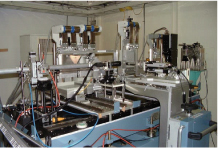 Fig. 3. X-ray scanning microscopy setup