トポ-トモグラフィ法を兼ね備えた白色X線トポグラフィ

Inquiry number
SOL-0000001526
Beamline
BL28B2 (White Beam X-ray Diffraction)
Scientific keywords
| A. Sample category | inorganic material |
|---|---|
| B. Sample category (detail) | semiconductor, crystal |
| C. Technique | X-ray diffraction |
| D. Technique (detail) | |
| E. Particular condition | 3D imaging (cf. CT) |
| F. Photon energy | X-ray (> 40 keV) |
| G. Target information | dislocation, strain |
Industrial keywords
| level 1---Application area | Semiconductor |
|---|---|
| level 2---Target | silicon semiconductor |
| level 3---Target (detail) | SOI, substrate |
| level 4---Obtainable information | d-spacing (lattice parameter), structure |
| level 5---Technique | imaging |
Classification
A80.12 semiconductor, M10.10 single crystal diffraction
Body text
トポ-トモグラフィ法は単結晶中のひずみ(転位など)の三次元構造をイメージとして観察できる手法です。この手法を白色X線トポグラフィ法と同時に行うことで、転位の三次元的な位置情報だけでなく、転位の性質(種類、バーガースベクトルやすべり面)も知ることができます。図は、典型的なCZシリコンのネック部のトポグラフィとその解析結果の模式図です。
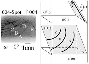
図 CZシリコンネック部のトポグラフ像と転位の解析結果
[ S. Kawado, T. Taishi, S. Iida, Y. Suzuki, Y. Chikaura, K. Kajiwara, Journal of Synchrotron Radiation 11, 304-308 (2004), Fig. 4, 6,
©2004 International Union of Crystallography ]
Source of the figure
Original paper/Journal article
Journal title
S. Kawado, T. Taishi, S. Iida, Y. Suzuki, Y. Chikaura and K. Kajiwara J. Synchrotron Rad. (2004). 11, 304-308
Figure No.
4
Technique
図1に示すように一つの回折スポット(この場合004回折スポット)に注目し、試料を回転させることでトポグラフ像によるCTを再構成する。これにより転位線の三次元的な位置情報が得られる。また、これと同時に、図2に示すような白色X線トポグラフィを行い、転位の性質(バーガースベクトルなど)を決定する。
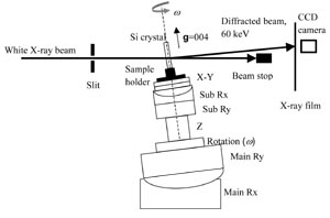
図1. 実験レイアウト。回転軸ωと垂直な面を回折面に選ぶことにより、試料を回転させてもトポグラフ像は移動しない。
[ S. Kawado, T. Taishi, S. Iida, Y. Suzuki, Y. Chikaura and K. Kajiwara, Journal of Synchrotron Radiation 11, 304-308 (2004), Fig. 1,
©2004 International Union of Crystallography ]
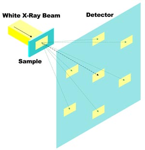
図2. 白色X線トポグラフィ。それぞれの回折スポットが回折指数の異なるトポグラフ像になっている。
Source of the figure
Original paper/Journal article
Journal title
S. Kawado, T. Taishi, S. Iida, Y. Suzuki, Y. Chikaura and K. Kajiwara J. Synchrotron Rad. (2004). 11, 304-308
Figure No.
1
Required time for experimental setup
8 hour(s)
Instruments
| Instrument | Purpose | Performance |
|---|---|---|
| ビームモニタ、CCDカメラ | 検出器 | 実効ピクセルサイズ5.83 μm |
| フィルム | 検出器 |
References
Related experimental techniques
トポ-トモグラフィ
Questionnaire
The measurement was possible only in SPring-8. Impossible or very difficult in other facilities.
Ease of measurement
With a great skill
Ease of analysis
Middle
How many shifts were needed for taking whole data in the figure?
Four-nine shifts