Switching of X-ray photon helicities at kHz range
Inquiry number
SOL-0000001128
Beamline
BL29XU (RIKEN Coherent X-ray Optics)
Scientific keywords
| A. Sample category | research on method, instrumentation |
|---|---|
| B. Sample category (detail) | magnetic material |
| C. Technique | X-ray diffraction |
| D. Technique (detail) | magnetic scattering, MCD, LD |
| E. Particular condition | polarization (circular), time-resolved (slow) |
| F. Photon energy | X-ray (4-40 keV) |
| G. Target information | spin/magnetism |
Industrial keywords
| level 1---Application area | storage device |
|---|---|
| level 2---Target | HD,MO |
| level 3---Target (detail) | magnetic layer, magnetic head, spin valve |
| level 4---Obtainable information | magnetic moment |
| level 5---Technique | XMCD, magnetic scattering, magnetic Compton scattering, PEEM |
Classification
A80.14 magnetic materials, M25.10 magnetic scattering, M40.30 XMCD
Body text
In this solution, a galvano optical scanner was applied to switching of X-ray photon helicities at kHz range. The scanner was used to oscillate a diamond crystal of X-ray phase plate quickly and accurately. This technique greatly enhances switching frequency to 2 kHz, from 100 Hz by a existing piezo method. Additionally, degree of circular polarization (PC) is nearly 100%. The technique can be combined with a lock-in detection to improve experimental accuracy in X-ray magnetic circular dichroism spectroscopy or X-ray magnetic scattering experiments.
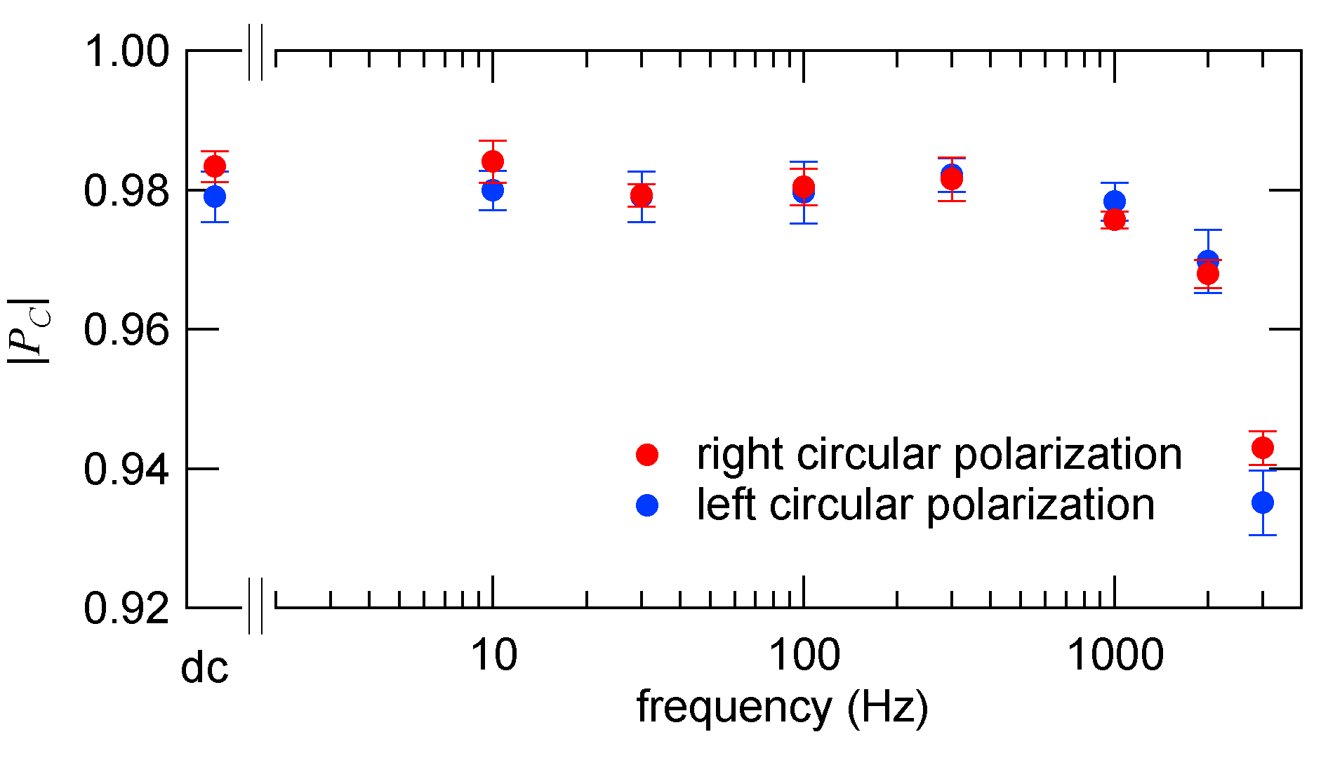
Fig. Degree of circular polarization (PC) as a function of the helicity switching frequency.
[ M. Suzuki, N. Kawamura and T. Ishikawa, Review of Scientific Instruments 74, 19-22 (2003), Fig. 4,
©2003 American Institute of Physics ]
Source of the figure
Original paper/Journal article
Journal title
Rev. Sci. Instrum. 74, 19 (2003).
Figure No.
Fig. 4
Technique
kHz photon helicity switching is performed by oscillating a diamond phase plate crystal using an optical scanner. The figure shows a photograph of a optical scanner mounting a phase plate crystal.
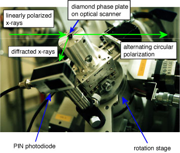
Fig. An optical scanner mounting a diamond phase plate crystal.
[ M. Suzuki, N. Kawamura and T. Ishikawa, Review of Scientific Instruments 74, 19-22 (2003), Fig. 1,
©2003 American Institute of Physics ]
Source of the figure
Original paper/Journal article
Journal title
Rev. Sci. Instrum. 74, 19 (2003).
Figure No.
Fig. 1
Required time for experimental setup
2 shift(s)
Instruments
| Instrument | Purpose | Performance |
|---|---|---|
| Optical scanner | Oscillating a diamond phase plate crystal | Maximum frequency 2 kHz |
References
| Document name |
|---|
| M. Suzuki, N. Kawamura, and T. Ishikawa, Rev. Sci. Instrum. 74, 19 (2003). |
Related experimental techniques
modulation spectroscopy, helicity modulation technique, XMCD, X-ray magnetic circular dichroism, X-ray magnetic scattering, X-ray magnetic reflectometry
Questionnaire
Ease of measurement
Middle
Ease of analysis
Middle
How many shifts were needed for taking whole data in the figure?
Two-three shifts