Top-up Operation Starts at SPring-8 Storage Ring
- Release Date
- 07 Jun, 2004
- Accelerator
7 June 2004
Japan Synchrotron Radiation Research Institute (JASRI)
|
Accelerator Division (Director, Dr. Noritaka Kumagai) of JASRI (Director-General, Dr. Akira Kira) successfully started the top-up operation of the SPring-8 storage ring. In the top-up operation, beam is injected with short intervals during user beamtime, and the current stored in the storage ring is kept constant. In the conventional operation, on the other hand, the stored current decayed with time and during beam injections, user experiments were interrupted due to beam orbit instabilities. Therefore, we were hard-pressed to come up with improvement measures. |
1. Background
For precise experiments with synchrotron radiation (SR)*1, stable high brilliance X-ray beams for a long experimental period is essential. To generate high brilliance X-ray, circulating electrons, the sources of SR, must be packed into a narrow phase space as an electron bunch with high density. However this kind of high-density state enhances coulomb scattering between the electrons in the same bunch and consequently shortens beam lifetime. That is, further performance improvement causes a reduction in beam lifetime. And that is why top-up operation can be a promising solution to this problem; the lost electrons are topped up by injecting new electrons and the stored current is kept constant. Although the top-up operation has no theoretical limit, it has the following three technical problems:
(1) Beam injection causes the stored beam oscillation and SR experiments are interrupted.
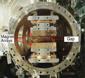
(2) Injected electron beam collides with permanent magnet-arrays of in-vacuum insertion devices (IDs) *2 and demagnetizes the permanent magnets.
(3) Frequent beam injections affect single bunch purity; the stored beam oscillation caused by frequent injections with short intervals, say, one-minute intervals, have a critical impact on precise SR experiments.
Many researchers visit SPring-8 from Japan and around the world to conduct unique and accurate experiments with stable high brilliance X-ray. To meet the users' needs for further innovative experiments at SPring-8, we needed to immediately realize the "ideal top-up operation" of the SPring-8 storage ring by solving the above three problems, so users will no longer be interrupted during their experiments.
2. Method and Results
2.1. Measures for Stored Beam Oscillation
As well as other third-generation light sources, sextupole magnets*3 are arranged in the injection bump orbit to enlarge the dynamic aperture. Although these sextupole magnets improve beam lifetime and injection efficiency, they inevitably cause the stored beam oscillation synchronizing with beam injections. To solve this problem, we firstly introduced the minimum condition for emittance of the injection bump leakage, which enables us to suppress the leakage down to a few tens micron keeping the dynamic aperture large enough for the stable beam injection (Figure 1).
Besides satisfying the minimum condition, field errors of four injection bump magnets*4 were improved by changing material of endplates from a metal to nonmetal, adjusting the impedance of bump magnets including power cables and correcting the magnet tilt errors. At last we corrected the remaining oscillation by a fast feed-forward correction system with an arbitrary waveform generator*5. As a result of all the above countermeasures, the stored beam oscillation was reduced down to the low level, which is negligible for all kinds of SR experiments (Figure 2).
2.2. Measures for Injection Beam Loss
In the SPring-8 storage ring, various kinds of in-vacuum IDs are installed. The IDs can change energy of emitted photons freely within a designed usable range by controlling its gap height between upper and lower permanent magnet arrays. This gap height is set to be narrow (minimum of 7mm in full height) to generate brilliant X-ray beam efficiently.
Electron beam injected into the storage ring decays and homogenizes to the stored beam oscillating in the horizontal plane. In this decay process, the horizontal oscillations of part of the injected electrons are converted to the vertical ones and such electrons are lost by hitting the permanent magnets of the ID whose gap height is set to be narrow and demagnetize the magnet. Computer simulations showed that some coupling resonance lines closely relating to an energy oscillation play important roles in this energy-exchange. The simulations also showed that the reduction in both chromaticity*6 and the horizontal amplitude of the injected beam is effective to suppress the injection beam loss.
Based on these results, we installed a collimator system processing the horizontal distribution of the injected electrons at the beam transport line to the storage ring. We also developed a suppression system on beam instabilities and installed it in the storage ring. By these countermeasures, the injection beam loss was suppressed down to the sufficiently low level even with the ID gap height close to their minimum values.
2.3. Formation of Purified Single-bunch
To measure a phenomenon with response time from nano seconds to micro seconds by using X-ray as a probe, a high level of single bunch purity is required. The impurity represents a background level for this kind of measurement. At SPring-8, a single bunch is formed in the booster synchrotron (full energy injector for the storage ring) by using an RF knock-out (KO) system, which kicks out stray electrons found around the main bunch. This is because the impurity scarcely increases in the storage ring due to strong radiation damping. By stabilizing all components of the
synchrotron and optimizing the RF accelerating voltage and so on, the impurity constantly reaches to the extremely low level which is undetectable by a simple photon counting method.
By combining with the above three developments, the ideal top-up operation which will not interrupt any SR experiment has been accomplished. It took six years since the kick-off meeting held in January 1999.
3. Perspectives deviation
(1) Based on the experimental verification of the operation performance, the top-up operation of the SPring-8 storage ring was introduced to user beamtime on May 20, 2004 (the fourth cycle). The injection interval is 1 minute and less than 0.1%. of beam current variation is attained (Figures 3 and 4). Continuous efforts have been made to further stabilize the stored beam current.
(2) Thermal stability of X-ray optics receiving high intensity X-ray beam is improved by the stabilization of the stored beam current, compared with that in the conventional operation. This thermal stability markedly assists to the highly accurate experiments. Thermal stability of the accelerators is also improved and electron beam orbit itself becomes more stable.
(3) The time-averaged brilliance is increased by a factor of two, compared with that obtained in the conventional operation. Dead time after beam injections*7 disappears in the top-up operation and users can perform their experiments more efficiently. Furthermore, especially in special experiments using SR from specific isolated bunches with high bunch current, enormous increase in brilliance by a factor of four or more is expected.
(4) A new filling pattern with high bunch current is available, which is not available in the conventional operation due to the extremely short beam lifetime. This will open the door to new SR experiments with intense pulsed X-ray.
<<Figures:>>
the horizontal plane by using the ideal half-sine field shape.
The old scheme (red line) causes the stored beam oscillation whose amplitude is 1.5mm in rms. It is found that the amplitude induced by the new scheme (light green line) is quite small, only 0.04mm in rms. The rms horizontal beam size (1σ in Gaussian distribution) at the ID source point is about 0.3mm.
According to progress of the leakage suppression, one can see that the induced horizontal beam oscillation is reduced step by step. The red close circles, blue open circles, green crosses and yellow open diamonds show the beam oscillation amplitudes before the improvement, after sextupole optimization, after both sextupole optimization and bump field correction and simulation result with both sextupole optimization and bump field correction, respectively.
the top-up operation: 10 a.m., May 20 to 10 a.m., May 26, 2004.
One sees that the stored current of the storage ring is kept constant at 99 mA.
May 23 to midnight, May 24, 2004 (a part of Fig. 3 is magnified).
One sees that the variation of the stored current is suppressed down to less than 0.1%. The full scale of the vertical axis is 0.1%.
Technical Terms
1. Synchrotron radiation:
Synchrotron radiation: Synchrotron radiation is emitted when a fast electron interacts with a magnetic field. A magnetic field causes the electron to change direction by exerting a force on it perpendicular to the direction the electron is moving. As a result, the electron is accelerated and radiates electromagnetic wave called synchrotron radiation. At SPring-8, two types of magnet structures are used: one is bending magnets to maintain the beam in a closed and stable orbit, and the other is insertion devices to enhance the brightness, extend or narrow the radiation spectrum and modify the spatial and temporal coherence of the beam.
2. In-vacuum insertion device:
An insertion devise (ID) is special magnet arrays providing a specific periodic field pattern to generate characteristic SR required to specific experiments. This device is installed in a magnet-free straight section of the storage ring. The ID of which magnet arrays are contained in a vacuum vessel is called "in-vacuum insertion device." The IDs are categorized into two kinds, an undulator and a wiggler. The undulator undulates the running electron beam periodically with small amplitude. Since the emitted SR at each undulation interfere mutually, undulator generates brilliant SR with a specific wavelength. The wiggler wiggles the running electron beam several times with relatively large amplitude. The wiggler generates the white light with shorter wavelength.
3. Sextupole magnet:
This magnet provides a correction of a focusing force in accordance with energy deviation as electrons with different energies receive the same integrated focusing force in one revolution. A field of the sextupole magnet is proportional to the square of horizontal deviation from a reference orbit. Due to this field, the sextupole magnet gives an extra focusing force to the electrons with relatively high energy and conversely gives an extra defocusing force to the electrons with relatively low energy. The sextupole magnet has six poles and its name originates from this characteristic shape.
4. Injection bump magnet:
This magnet bends a reference orbit nearby an injection point toward injection electrons approaching to a storage ring (to the inside of the ring at SPring-8) in a short period (eight microseconds) synchronizing to the injected electrons. This action puts the injected electrons around the reference orbit with small amplitude and helps the injected electrons to accumulate in the ring. In bending the orbit toward the injected electrons, the reference orbit is distorted locally like a bump and this is an origin of the name.
5. Arbitrary waveform generator:
This device generates and outputs a complicated pattern signal required for a specified purpose by using a provided sine-wave, rectangular wave, triangle wave, pulse wave and calculated data. On the basis of the generated signal, the current pattern is formed for the fast correction of the remaining stored beam oscillation.
6. Chromaticity:
Chromaticity is an indicator to represent difference of a focusing force received by a circulating electron in one revolution depending on difference of the electron energy. A Betatorn tune is the number of a betatron oscillation in one revolution and the chromaticity is defined as the betatron tune-shift occurred when the energy of a circulating electron increases by 100%.
7. Dead time after beam injections:
When electron beams are refilled with photon beam shutters closed or large difference of a stored beam current is occurred before and after beam injections, thermal equilibrium of X-ray optics receiving intense SR is broken. The X-ray optics therefore becomes unstable after beam injections while the thermal equilibrium recovers. This X-ray optics instability is an obstacle to precise experiments and such experiments are usually suspended in this unstable period. This period is called dead time after beam refilling.
|
For further information, please contact: |
- Previous Article
- Structure of the human DNA recombinase reveals a double ring- Homologous pairing takes place at the central channel of the ring - (Press Release)
- Current article
- Top-up Operation Starts at SPring-8 Storage Ring