Analyzing Nanospatial Distribution in Polymer Electrolyte Fuel Cell Catalysts at the Unique Beamline with the Best Performance in the World for Fuel Cell Analysis -Spatial distribution of platinum species in fuel cell catalyst layers observed using nano-
- Release Date
- 22 Oct, 2014
- BL36XU (Catalytic Reaction Dynamics for Fuel Cells Beamline)
The University of Electro-Communications
apan Synchrotron Radiation Research Institute (JASRI)
Key points
• The research group succeeded in mapping the degradation of fuel cell catalysts at the unique beamline BL36XU at SPring-8 with the best performance in the world for fuel cell catalyst analysis, which was constructed by the University of Electro-Communications under a New Energy and Industrial Technology Development Organization (NEDO) program.
• The research group succeeded in the two-dimensional mapping of platinum (Pt) species in electrode catalyst membranes and in the identification of dissolved species using the nano-X-ray absorption fine structure (XAFS)*1 technique with the highest spatial resolution in the world.
• These achievements will promote the development of electrode catalysts for next-generation fuel cells, enabling the widespread use of fuel-cell-powered cars, and provide new scientific guidelines for the development and design of electrode catalysts.
|
1.Determination of the cause and mechanism of fuel cell degradation is desired because significantly improving the durability of electrode catalysts in polymer electrolyte fuel cells (PEFCs)*2is one of the key requirements for realizing the widespread use of fuel-cell-powered cars. However, direct observation of the catalysts has been very difficult. The research group has developed a technique to directly observe catalysts that are spatially distributed. Publication: |
<<Achievements>>
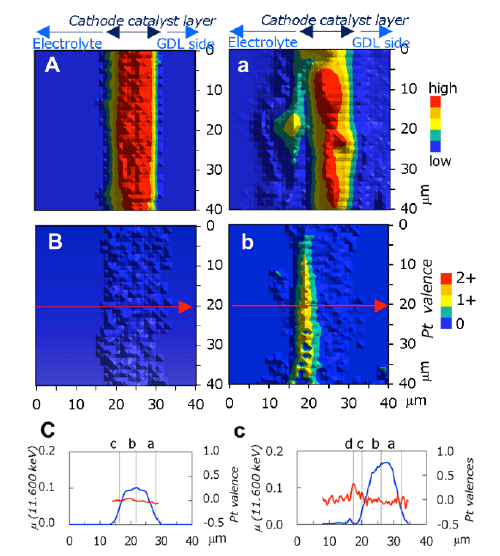
A: Pt mapping before degradation
B: Pt valence mapping before degradation (metal Pt found throughout the layer)
C: Line profile along arrow in B [Pt amount (blue) and Pt valence (red)]
a: Pt mapping after degradation (heterogeneous)
b: Pt valence mapping after degradation (Pt ions localized in yellow region)
c: Line profile along arrow in b[Pt amount (blue) and Pt valence (red)]
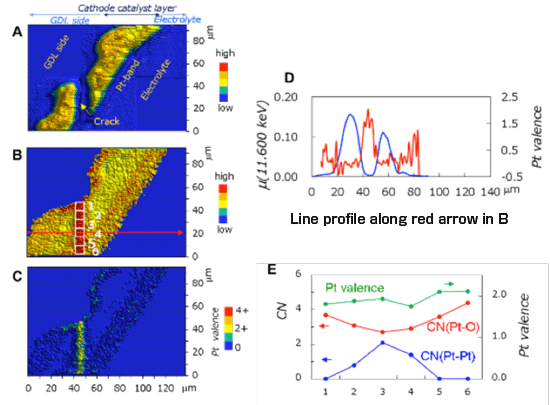
A: Pt mapping after degradation
B: Mapping of white line peak intensity of X-ray absorption near-edge structure (XANES) spectrum after degradation
C: Pt valence mapping (Pt2+ ions dissolved in yellow region)
D: Line profile along arrow in B [Pt amount (blue) and Pt valence (red)]
E: Pt valence (green) and coordination numbers of Pt-O (red) and Pt-Pt (blue) obtained by XAFS measurements at numbered sites in the micro-crack region in B
《Glossary》
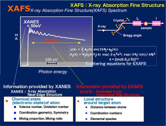
※1 X-ray absorption fine structure (XAFS)
Most solid catalysts such as fuel cell catalysts are fine nanoparticles not having a crystal-like periodic structure and being dispersed on the surface of carriers such as carbon. X-ray diffraction (XRD), used to analyze a crystal structure, cannot be applied to such catalysts. Also, the molecular structure including chemical bonding cannot be determined by electron microscopy because it is performed under high vacuum. The XAFS technique is very effective in analyzing the local structure of solid catalysts. When a substance is irradiated with X-rays, electrons are expelled from the target atom through X-ray absorption and scattered and interfered by neighboring atoms. A fine structure is observed in the X-ray absorption spectrum at that time, which is called XAFS.
As shown in Fig. 1, the X-ray absorption spectrum includes an X-ray absorption near-edge structure (XANES) and an extended X-ray absorption fine structure (EXAFS). XANES provides information on the oxidation number and symmetry of the target atom as well as the proportion of the substances in a mixture. EXAFS provides information on the local structure such as the type and number of atoms neighboring the target atom and the distance between the atoms.
Because of the use of hard X-rays with high penetrating power, the XAFS technique has the following characteristics: (1) it is hardly affected by the form and type of samples (crystals, amorphous materials, devices, liquids, gases, and biological materials); (2) it can be performed not only in a limited atmosphere but also under various conditions including an in situ environment and reaction conditions; (3) it is applicable to a mixture of multiple elements; (4) it is highly sensitive even to the order of a ppm concentration and a 0.1-nm-thick thin film. On the other hand, the disadvantage of XAFS is that this technique only provides information on the average structure. Despite this disadvantage, XAFS is the only technique that can analyze the molecular structure of many catalysts such as chemical process catalysts consisting of metallic nanoparticles heterogeneously dispersed and supported on the surface of a carrier, automobile catalysts, fuel cell catalysts, and environmental catalysts that cannot be analyzed by XRD. Therefore, the XAFS technique is particularly effective for the in situ analysis of fuel cell electrode catalysts under operating conditions that have hardly been studied using other analytical techniques. XAFS spectroscopy using synchrotron radiation has been established as a leading technique to analyze the structure of various solid catalysts.
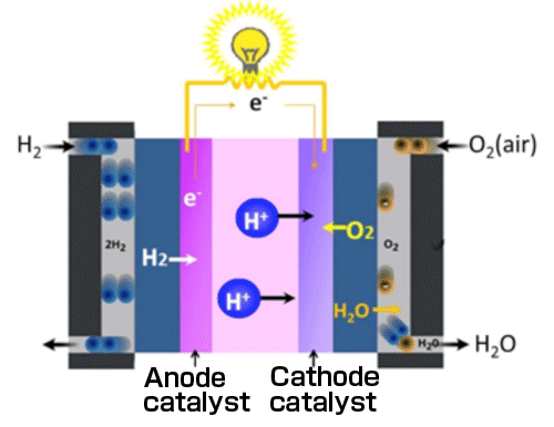
※2 Polymer electrolyte fuel cell (PEFC)
PEFC is a fuel cell that uses an ion conductive polymer membrane (ion-exchange membrane) as its electrolyte. PEFC has a stacked structure in which a membrane electrode assembly (MEA) consisting of a fuel electrode (anode), a solid polymer electrolyte membrane, and an air electrode (cathode) bonded together is sandwiched between a pair of conductive plates each having a reaction gas supply path therein (Fig. 2). Anode and cathode catalysts are generally Pt nanoparticles supported on carbon carriers.
For more information, please contact: For more information on press relations, please contact: |


- Current article
- Analyzing Nanospatial Distribution in Polymer Electrolyte Fuel Cell Catalysts at the Unique Beamline with the Best Performance in the World for Fuel Cell Analysis -Spatial distribution of platinum species in fuel cell catalyst layers observed using nano-