Microtomographic observation of tumor blood vessels
Inquiry number
SOL-0000001182
Beamline
BL20B2 (Medical and Imaging I)
Scientific keywords
| A. Sample category | biology, medicine |
|---|---|
| B. Sample category (detail) | organism, cell |
| C. Technique | absorption and its secondary process |
| D. Technique (detail) | |
| E. Particular condition | 3D imaging (cf. CT) |
| F. Photon energy | X-ray (4-40 keV) |
| G. Target information | morphology |
Industrial keywords
| level 1---Application area | Pharmaceuticals, others |
|---|---|
| level 2---Target | drug design |
| level 3---Target (detail) | drug, organism |
| level 4---Obtainable information | molphology |
| level 5---Technique | imaging |
Classification
A80.90 others, M60.20 X-ray CT
Body text
A rabbit auricle specimen implanted with a carcinoma was fixed in formalin and sealed up in the specimen case after a barium sulphate solution was injected into blood vessels as a contrast agent. Projection images were recorded from 1800 views during 180-degree rotation. 3D images of the specimen shown in Fig. 1 were obtained by tomographic reconstruction, and small blood vessels induced by the tumor were demonstrated. An avascular area in the central portion was dead tumor tissue. In contrast, the number of blood vessels increased remarkably around the avascular area, where tumor cells were vital and a tumor's growth rate was rapid.
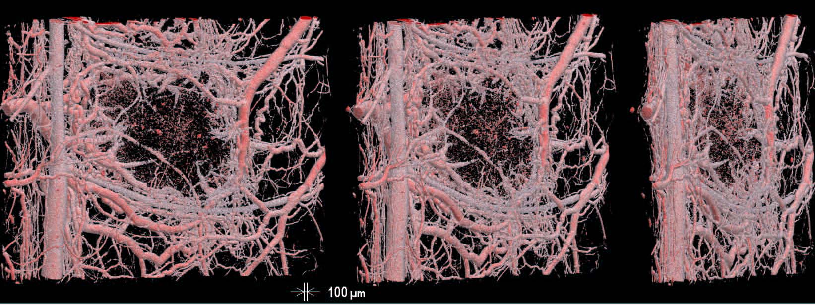
Fig. 1. 3D images of the tumor encircled with the network of blood vessels induced by the tumor.
The images are displayed at viewing angles of 0 (a front view), 30, and 60 degrees, from left to right.
Source of the figure
Bulletin from SPring-8
Bulletin title
SPring-8 Research Frontiers 2004
Page
Technique
A micro-computed tomography (micro-CT) system was developed using a 10-megapixel CCD camera for 3D biomedical imaging. The detector consists of a beryllium window for X-ray incidence, a fluorescent screen, an optical mirror, high numerical aperture lenses and the CCD camera. X-rays are converted into a visible image in the screen with thickness of 10 µm. The screen and the mirror are built in behind the beryllium window. The mirror deflects the luminescent light 90° to the lens system that focuses it on the camera. An X-ray field of view is 24mm wide by 16 mm high (4024 x 2648 pixels); the pixel measures 6 µm by 6 µm.
Source of the figure
No figure
Required time for experimental setup
3 hour(s)
Instruments
| Instrument | Purpose | Performance |
|---|---|---|
| Micro-CT system | 3D-CT imaging | 10M pixels |
References
| Document name |
|---|
| SPring-8 Research Frontiers 2004 |
Related experimental techniques
No
Questionnaire
This solution is an application of a main instrument of the beamline.
Ease of measurement
Middle
Ease of analysis
Middle
How many shifts were needed for taking whole data in the figure?
Two-three shifts