Phase retrieval x-ray diffractometry
Inquiry number
SOL-0000001047
Beamline
BL29XU (RIKEN Coherent X-ray Optics)
Scientific keywords
| A. Sample category | research on method, instrumentation |
|---|---|
| B. Sample category (detail) | semiconductor |
| C. Technique | X-ray diffraction |
| D. Technique (detail) | coherent scattering, phase measurement |
| E. Particular condition | X-ray microscopy |
| F. Photon energy | X-ray (4-40 keV) |
| G. Target information | structure analysis |
Industrial keywords
| level 1---Application area | Semiconductor |
|---|---|
| level 2---Target | silicon semiconductor |
| level 3---Target (detail) | |
| level 4---Obtainable information | molphology |
| level 5---Technique | diffraction, imaging |
Classification
A80.20 metal ・material, A80.30 inorganic material
Body text
Phase retrieval x-ray diffractometry is a phase contrast imaging technique using analytic properties of the complex amplitude of the diffracted x-ray wave.
The following figures show the x-ray diffraction intensity profile and the reconstructed image of a micro-fabricated silicon pattern.
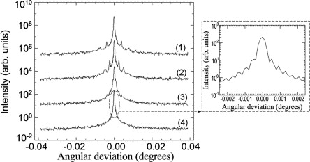
Fig. X-ray diffraction intensity profile of a micro-fabricated silicon pattern
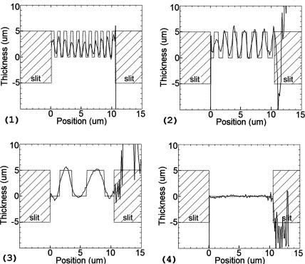
Fig. Variation of the sample thickness reconstructed from the x-ray diffraction intensity profile
[ A. V. Darahanau, A. Y. Nikulin, A. Souvorov, Y. Nishino, B. C. Muddle and T. Ishikawa, Optics Communications 251, 100-108 (2005), Fig. 2, 3,
©2005 Elsevier B. V. ]
Source of the figure
Original paper/Journal article
Journal title
A.V. Darahanau, A.Y. Nikulin, A. Souvorov, Y. Nishino, B.C. Muddle, and T. Ishikawa, Optics Communications 251, 100-108 (2005)
Figure No.
2,3
Technique
The x-ray diffraction intensity profile of a sample is measured by scanning the analyzer crystal angle.
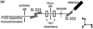
Fig. Experimental setup of phase retrieval x-ray diffractometry
[ A. V. Darahanau, A. Y. Nikulin, A. Souvorov, Y. Nishino, B. C. Muddle and T. Ishikawa, Optics Communications 251, 100-108 (2005), Fig. 1(a),
©2005 Elsevier B. V. ]
Source of the figure
Original paper/Journal article
Journal title
A.V. Darahanau, A.Y. Nikulin, A. Souvorov, Y. Nishino, B.C. Muddle, and T. Ishikawa, Optics Communications 251, 100-108 (2005)
Figure No.
1(a)
Required time for experimental setup
24 hour(s)
Instruments
References
| Document name |
|---|
| A.V. Darahanau, A.Y. Nikulin, A. Souvorov, Y. Nishino, B.C. Muddle, and T. Ishikawa, Opt. Commun. 251, 100-108 (2005) |
| A.V. Darahanau, A.Y. Nikulin, A. Souvorov, Y. Nishino, B.C. Muddle, and T. Ishikawa, Phys. Lett. A 335, 494-498 (2005) |
| A. Y. Nikulin, A. V. Darahanau, R. Horney, and T. Ishikawa, Physica B 349, 281-295 (2004) |
| K. Siu, A. Y. Nikulin, K. Tamasaku, and T. Ishikawa, Appl. Phys. Lett. 79, 2112-2114 (2001) |
| K. Siu, A. Y. Nikulin, K. Tamasaku, and T. Ishikawa, J. Phys. D: Appl. Phys. 34, 2912-2917 (2001) |
Related experimental techniques
Questionnaire
With user's own instruments.
Ease of measurement
With a great skill
Ease of analysis
With a great skill
How many shifts were needed for taking whole data in the figure?
Four-nine shifts