Introduction to SPring-8 Insertion Devices
Type of IDs installed in the SPring-8 Storage Ring
The contensts of IDs installed in SPring-8 are summarized in the table below.
| Beamline No. |
Type of ID |
Periodic Length (cm) | Number of Periods |
Minimum Gap (mm) | Maximum K Value |
| BL03XU | In-Vacuum | 3.2 | 140 | 8.1 | 2.58 |
| BL05XU | In-Vacuum | 3.2 | 93 | 8.24 | 2.54 |
| BL07LSU | Figure-8 | 10.0 | 26×4+20×4 | 28, 20 | -- |
| BL08W | Elliptical Wiggler | 12.0 | 37 | 25.5 | 0.5(Kx) 11.24(Ky) |
| BL09XU | In-Vacuum | 3.2 | 140 | 8.58 | 2.33 |
| BL10XU | In-Vacuum | 2.8 | 128 | 8 | 2.27 |
| BL11XU | In-Vacuum | 3.2 | 140 | 9.2 | 2.32 |
| BL12XU | In-Vacuum | 3.2 | 140 | 8.1 | 2.51 |
| BL13XU | In-Vacuum | 3.2 | 140 | 9.6 | 2.2 |
| BL15XU | Revolver(Linear Polarization) | 4.4 | 102 | 21.3 | 2.24 |
| Revolver(Circular Polarization) | 9.2 | 48 | 20 | 3.42 | |
| BL16XU | In-Vacuum | 4.0 | 112 | 12.9 | 2.38 |
| BL17SU | Multi-polarization-mode undulator | 13.0 | 34 | -- | -- |
| BL19LXU | In-Vacuum | 3.2 | 780 | 11.8 | 1.79 |
| BL20XU | In-Vacuum | 2.6 | 173 | 7 | 2.12 |
| BL22XU | In-Vacuum | 3.8 | 118 | 9.98 | 2.95 |
| BL23SU | Helical | 7.5 | 17x2 | 8 | 4.5 |
| BL24XU | In-Vacuum Figure-8 | 2.6 | 172 | 8 | 1.32(Kx) 1.66(Ky) |
| BL25SU | Helical | 12.0 | 12x2 | 20 | 6.47 |
| BL27SU | Figure-8 | 10.0 | 44 | 37 | 4.28(Kx) 6.90(Ky) |
| BL28XU | In-Vacuum | 3.2 | 140 | 8.1 | 2.59 |
| BL29XU | In-Vacuum | 3.2 | 140 | 8.86 | 2.53 |
| BL32XU | In-Vacuum | 2.6 | 173 | 7.4 | 2.01 |
| BL33XU | In-Vacuum | 3.2 | 140 | 8 | 2.6 |
| BL35XU | In-Vacuum | 2.0 | 225 | 6.64 | 1.49 |
| BL36XU | In-Vacuum | 3.2 | 140 | 8 | 2.59 |
| BL37XU | In-Vacuum | 3.2 | 140 | 8.5 | 2.46 |
| BL39XU | In-Vacuum | 3.2 | 140 | 8.6 | 2.33 |
| BL40XU | In-Vacuum Helical | 3.6 | 125 | 8.3 | 1.04 |
| BL41XU | In-Vacuum | 3.2 | 140 | 9.6 | 1.99 |
| BL43XU | In-Vacuum | 1.9 | 780 | 6.2 | 1.46 |
| BL44XU | In-Vacuum | 3.2 | 140 | 9 | 2.31 |
| BL45XU | In-Vacuum | 3.2 | 93 | 10.9 | 1.97 |
| BL46XU | In-Vacuum | 3.2 | 140 | 9.6 | 2.2 |
| BL47XU | In-Vacuum | 3.2 | 140 | 9.6 | 2.11 |
In-Vacuum Undulator(Standard, Hybrid, Vertical) In general, the magnet arrays of an insertion device (ID) are installed outside the vacuum chamber. In this case, the vertical inner aperture of the vacuum chamber should be larger than the vertical aperture required at the time of beam injection. The minimum magnet gap should be larger than this value by the thickness of the vacuum chamber. Taking into account the clearance between the vacuum chamber and magnet arrays, and the alignment error of the vacuum chamber, the minimum magnet gap should be wider than 20 mm. In order to tune a wide energy range using undulator radiation without energy gap, a K value larger than 2 is required. To meet this requirement, a periodic length longer than 5 cm is necessary for a minimum gap of 20 mm.
In SPring-8, the minium gap can be made as low as 8 mm by installing the magnet arrays inside the vacuum chamber, which makes it possible to adopt a periodic length of 32 mm as a standard ID. Using this device, a wide energy range from 5 to 80 keV is available with up to the 5th harmonic of the undulator radiation.
In-vacuum hybrid undulators utilize pole pieces made from high-permeability material (permendur) in order to enhance the magnetic field. Thus a shorter period (24 mm) than the standard in-vacuum undulator is available and the available energy range is slightly shifted to higher energy.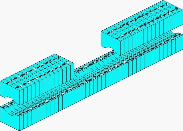 An in-vacuum vertical undulator is an ID to generate horizontal magnetic field and make the electron move in the vertical plane in order to provide vertically polarized radiation. The top and magnet arrays are divided into two arrays to generate horizontal field. In SPring-8, the surface profile of the magnet blocks is modified in order to improve the uniformity of the field profile in the horizontal direction.
For realization of the in-vacuum undulator, it is indispensable to achieve ultra high vacuum (UHV) in the vacuum chamber with the magnet arrays installed. TiN (titanimu nitride) coating on the magnet surface and bakeout under a precise temperature control of the magnet arrays are one of the technologies to realize UHV.
Helical Undulator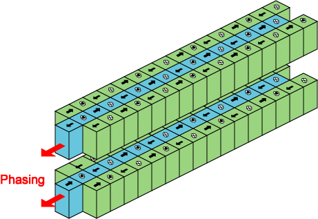 A helical undulator is an ID to make the electron move along a helix and to provide circularly polarized radiation. One of the most important characteristics of helical undulator radiation is that only the fundamental radiation is observed on axis. The users do not suffer from unwanted heat load brought by high harmonics and thus the helical undulator is an ideal ID from the viewpoint of photon flux. In SPring-8, three magnet arrays are installed at the top and bottom in order to generate the helical magnetic field. The central magnet array generates the vertical field ,while the outer arrays generate the horizontal field. In addition, by shifting the central array (phasing), it is possible to change the helicity (right- and left-handed) of the circular polarization.
At BL25SU, one of the soft x-ray beamlines in SPring-8, two helical undulators and 5 kicker magnets are installed in order to switch the helicity of circular polarization quickly. As shown in the figure, by inducing two triangle bump orbits alternately, the helicity of radiation observed on axis is switched. At present, a repetition rate up to 10Hz is available.
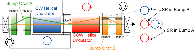
Figure-8 Undulator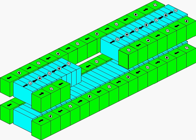 Because the electron energy of SPring-8 is very high, a high K value should be applied to obtain photons in the soft x-ray region with an undulator. As far as a conventional linear undulator is concerned, higher K value results in larger intensity in high hamonics, which leads to unwanted heat load on optical elements. If the users need circular polarization , or do not need polarization properties, helical undulators can be adopted to reduce the heat load. The figure-8 undulator is an ID to provide linear polarization with much less heat load than the conventional linear undulator. In the figure-8 undulator, the eletron moves along a special trajectory that looks a figure of eight when projected onto the transverse plane. In order to create the figure-8 orbit, the SPring-8 helical undulator is slightly modified by doubling the periodic length of the outer arrays. This means that the periodic length of the figure-8 undulator is twice that of the horizontal field, for convenience, however, the fundamental radiation genereated by the horizontal field is called the 0.5th harmonic, and that by the vertical field is called the 1st harmonic. In addition, the 0.5th, 1.5th, and 2.5th (half-odd integer) harmonics have the vertical polarization, while the 1st, 2nd and 3rd (integer) harmonics have the horizontal polarization.
Elliptic Wiggler
When the synchrotron radiation from the bending magnet is observed off axis, circularly polarized radiation is obtained with the degree of polarization determined by the observation angle. This is a consequence of the fact that the electron's circular motion, which cannot be seen from the orbital plane, is observed off axis. It should be noted, however, that circular polarization cannot be obtained when the radiation from a wiggler is observed off axis because the circularly polarized component is cancelled due to coherent sum of radiation emitted at adjacent periods. The elliptic wiggler is an ID to obtain circular polarization by avoiding the cancellarion: the electron is deflected slightly in the vertical direction at each pole of the magnetic field. The magnet configuration of the elliptic wiggler is the same as that of the helical undulator.