Topics
(1) Precision temperature control in acceleration columns
1. Necessity of precision temperature control
When an average of 25 MW is supplied to the acceleration columns, the energy is used to accelerate electron beam. However, part of the lost energy increases the wall temperature of the acceleration column. As a result, a dimensional change in the acceleration column is induced leading to a discrepancy of frequency.
This phenomenon significantly affects the efficiency of the acceleration column. Therefore, it is necessary to uniformly and precisely control the temperature of the entire surface wall of the acceleration column.
When cooling water is directed into the acceleration column, a temperature gradient is induced in the axial direction of the acceleration column. (This tendency is more common in longer acceleration tubes.) To make the temperature uniform over the entire outer peripheral surface of the acceleration column, cooling water is passed through eight paths on the wall of the acceleration column. The directions of the cooling water in two neighboring paths are opposite to each other, with the direction of the cooling water in each path reversing alternately.
2. Outline of temperature control of purified water cooling system in acceleration column
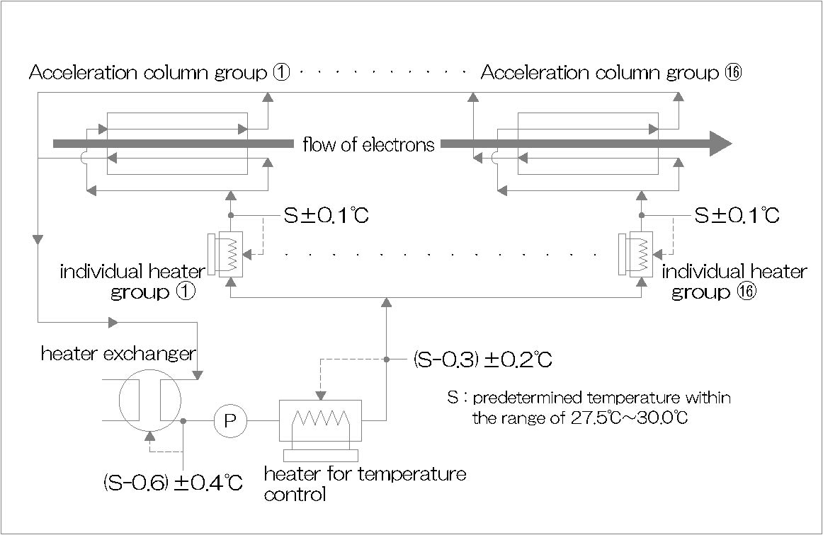
The heat generated in the acceleration column is transferred to the cooling water (purified water with specific resistance of 1 MΩ.cm or higher), and then transferred to cool water (industrial water, 25°C) via a heat exchanger. The heat is then released into the air from the cooling tower via a refrigerator. The supply temperature of the cooling water required in the vicinity of individual acceleration columns, which are classified into 16 groups, is within ±0.1°C of the predetermined temperature. With the use of a conventional heat exchanger, the limit of the temperature stability is ±0.3°C ; therefore, the required temperature is not attained by one temperature control cycle. In addition, to achieve a maximum temperature difference of ±0.1°C from the target temperature, a detection accuracy of ±0.05°C or better is required for both the temperature sensor and transformer.
The purified water cooling system of the acceleration column is designed so that temperature deviation is minimized by a three-step temperature control to achieve the target temperature (27.5°C - 30.0°C) and a temperature deviation of ±0.1°C. Step (1) is a conventional cooling process using a heat exchanger to control the cooling water temperature to the target temperature, -0.6°C ± 0.4°C. In step (2), a temperature-controlled heater (electric capacitance: 90 kW) is used. In step (3), 16 heaters (electric capacitance: 1 - 12 KW) are used to precisely control the temperature by heating (maximum 0.3°C). Finally, the temperature in the vicinity of the 16 groups of acceleration columns (outlet of individual heaters) is controlled to the target temperature ±0.1°C.
The resistor for measuring the temperature of cooling water is the JPt standard 200 Ω at 0°C (calibration accuracy ± 0.0022°C) platinum resistor, instead of the conventional JIS Pt 100 Ω platinum resistor, to increase the resolution. The overall deviation, that is, the combined deviations of the resistance bulb and the temperature transformer, is ±0.03°C. Accuracy refers to both accuracy and precision; the resistance bulb (200 Ω) and temperature transformer are periodically calibrated to ensure the reliability of the measurement results and traceability.
(2) Static var compensator (SVC)
A change in reactive power due to a change in load or an accident in the electric system induces voltage change at various locations throughout the system.
Once a voltage change exceeding the allowable limit arises, adverse effects such as the interruption of the normal operation of the equipment and flicker illumination are induced. As a countermeasure, SVC is used.
At the substations, SVC, which enables high-speed control of reactive power, is introduced to supplement the stable control of the functions of the electric system for the purpose of suppressing voltage change.
With SVC, the reactive power is compensated by continuously changing the current in the reactor. The current is controlled by thyristor phase control.