Three-dimensional observation of micro structure evolution in micro-solder balls


Inquiry number
SOL-0000000934
Beamline
BL47XU (Micro-CT)
Scientific keywords
| A. Sample category | inorganic material |
|---|---|
| B. Sample category (detail) | metal, alloy, ferroelectric material, insulator, ceramics, crystal |
| C. Technique | absorption and its secondary process |
| D. Technique (detail) | |
| E. Particular condition | 3D imaging (cf. CT), time-resolved (slow) |
| F. Photon energy | X-ray (4-40 keV) |
| G. Target information | dislocation, strain, structural change, morphology |
Industrial keywords
| level 1---Application area | Semiconductor, electric component, mechanics |
|---|---|
| level 2---Target | silicon semiconductor |
| level 3---Target (detail) | wire |
| level 4---Obtainable information | density, structure |
| level 5---Technique | imaging |
Classification
A80.10 electronics, A80.12 semiconductor, A80.20 metal ・material, A80.30 inorganic material, M60.20 X-ray CT
Body text
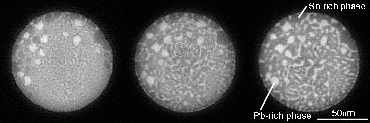
Micro-tomography is a powerful technique to study internal structures of materials. Using this technique, one can measure the micro structures of microjoinings on PCB (Printed Circuit Board). The distribution of the constituent phases in Sn-Pb eutectic solder was identified based on the estimation value of X-ray linear attenuation coefficient. And the phase growth process due to cyclic thermal loading was determined by the observation of the CT images obtained consecutively at the fixed point of the target joining. The figure shows the CT images of same solder ball at the different time (after the heat loads). These data reveal the micro-tomography can be used for evaluation of fatigue lifetime of micro joinings.
[ T. Sayama, H. Tsuritani, K. Uesugi, A. Tsuchiyama, T. Nakano, H. Yasuda, T. Takayanagi and T. Mori, Proceedings of 11th Symposium on "Microjoining and Assembly Technology in Electronics" 11, 189-194 (2005), Fig. 7,
©2005 Japan Welding Society ]
Source of the figure
Original paper/Journal article
Journal title
エレクトロニクスにおけるマイクロ接合実装技術シンポジウム論文集, Vol. 11 (2005), pp. 189-194.
Figure No.
fig7
Technique
Source of the figure
No figure
Required time for experimental setup
3 shift(s)
Instruments
| Instrument | Purpose | Performance |
|---|---|---|
| X-ray CT system | obtaining internal structures of materials | spatial resolution of about 1µm |
References
Related experimental techniques
Questionnaire
The measurement was possible only in SPring-8. Impossible or very difficult in other facilities.
This solution is an application of a main instrument of the beamline.
Ease of measurement
Easy
Ease of analysis
Middle
How many shifts were needed for taking whole data in the figure?
Two-three shifts